|
       |
813 Amplifier Schematic Diagram
WARNING
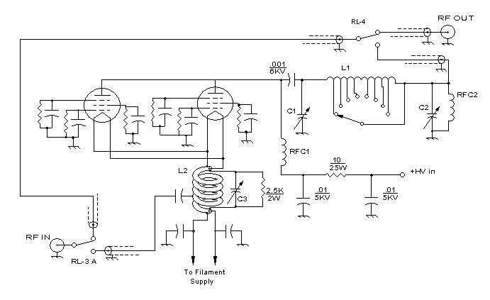
Note: All unmarked capacitors are .01 uFd @ 1KV.
All unmarked resistors are 4.7 ohm @ 2 watt
Parts List
| C1 150 pF variable 0.125 spacing | L2 See next page for details |
| C2 1200 pF 3 section AM receiver variable | RFC 1 (2) 3/4" dia. 3" long 24 AWG (see text) |
| C3 900 pF 2 section variable | RFC 2 2.5 mH |
| L1 3" Dia. 13 turns - see text | RL-3 DPDT relay 10A contacts |
As you can see, this is a typical 813 amplifier schematic with the exception of the input circuit. This is known as a "bifilar tuned input". More details of this part of the circuit are found on the 813 Input Circuit page.
L1 is actually two coils in series. The first coil is 3" diameter coil with 0.25" spacing. with taps for the following bands:
| 80 Meters | 13 Turns |
| 40 Meters | 7 Turns |
| 30 Meters | 4 Turns |
The second coil is 4 turns of 1/4" copper tubing 2" diameter with 0.5" spacing. with taps for the following bands:
| 20 Meters | 3 Turns |
| 17-15 Meters | 2 Turns |
| 10 Meters | 1 Turns |
RFC 1 is actually made up of two seperate chokes. Each one is close-space wound on a 3/4"
diameter ceramic rod 3 1/2 inches long using 24 AWG enamel wire. The two chokes are mounted
at right angles to each other, and have a .01 uF @ 5 KV bypass capacitor to ground between
the two chokes. This is an attempt to eliminate any self-resonance near the operating
frequencies of the 813 amplifier.
RFC 2 across the output is a mandatory safety item. Should the .001uF DC blocking capacitor ever break down, you will have the high voltage supply connected to the antenna system. This choke will shunt the DC to ground and open the fuses in the primary side of the plate transformers. Under no circumstances is this choke to be left out. Use 28 AWG enameled wire. Wind 150 turns on to a 2" ferrite rod. If you have to, you can wind the wire in 2-3 layers.
The T-R switching cicruit is composed of two 12 VDC relays. I chose to use two relays, RL-3 and RL-4, becuase I was concerned about coupling between the input and output of the amplifier. RL-3 is a DPDT relay that is energized during transmit. The second set of contacts are shown on the Filament Supply schematic. This relay is located in the input section of the amplifier. RL-4 also a DPDT relay and is located in the RF deck of the amplifier near RFC 2.