|
|
The Input Circuit
To date, this is what I am working on. I am departing from the typical input circuitry.
Instead, I am going to try a little known, but apparently very efficient circuit known
as a "bifilar tuned input" circuit. People such as ZL1AXB, and Joby,
N5APR get
1000 watts output from a pair of 813's using this circuit. Which by the way, you
typically get around 700 watts out. Needless to say this caught my attention, so I too
am going to try it.
Below is a photo of the input circuit:
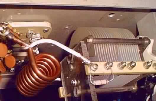
I used a piece of 1/4 inch copper tubing 31.5" long and slipped a
piece of Nr. 10 gage teflon coated wire inside it. The coil is 7 1/2 turns with an inside
diameter of one inch, spaced as close as possible without shorting out the turns.
One end of the coil is connected to the filaments of the 813
tubes, and the other end is connected to the filament supply. There is a dual gang
900 pf. air variable capacitor in parallel with the coil. This is then swamped with
a 2.5K 2 watt resistor.
This is as far as the project goes right now. As the cold weather approaches, I will have
more time to work on it. Stop back in a couple of months.
-- Mike
|


