|
       |
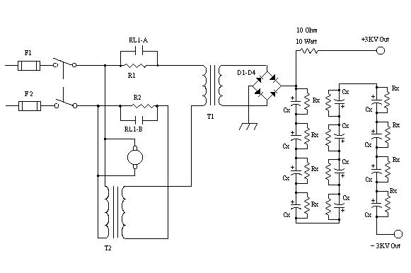
High Voltage Supply
WARNING
Parts List
| Cx 4700 Uf @ 350 volt Electrolytic | R1,R2 25 Ohm 10 watt |
| D1-D4 5000 PIV @ 1 amp | Rx 25K @ 5 Watt |
| F1,F2 15 Amp Slow Blow | T1 2600 VAC @ 1 amp |
| RL1 120 VAC Delay on Operate | T2 12 VAC @ 10 amps |
A lot of the parts used in this project came with the transmitter. As a result I had to get a bit creative to get what I wanted. In doing a bit of research, I found out that several people have run 813 tubes with 3Kv sucessfully with out damage. Based on what I had, I decided to change the power supply filter from a choke input filter to a capacitor input filter. I found a great deal on some 4700 Uf @ 350 V capacitors. So I bought 12 of them, and put them in series (Cx above). This gives me an equivalent capacitor of 390 Uf @ 4200 volts. Yes, I know this is overkill, but hey, they were cheap, and I had the room! This brought me to my next problem. When I wired in all of the caps, and fired it up, I had 3200 volts. I felt that was too much for the 813's so I found a low voltage transformer to put in series with the primary of the main transformer as a "bucking" transformer (T2). This then dropped my output voltage to the 3000 volts I wanted. Once again, this is not the best way, but I was able to find a transformer cheap.
For those who don't know, a "bucking" transformer you take the secondary winding and put it in series but out of phase with the primary of the main transformer. What happens is that the net voltage applied to the main transformer is reduced, and therefore the output voltage of the main transformer is reduced.
Usually High voltage supplies have a "step start" circuit. This one is no different. The purpose of the step start circuit is to apply power at a reduced voltage so as to limit the initial inrush current. After a period of time, the step start circuit energizes, and applies full input voltage. I felt this was very necessary since my filter capacitor is larger than typical. I was able to find a nice programmable "delay on operate" relay (RL1) at the local surplus store for a good price along with the current limiting resistors (R1 and R2).
After running some tests, I found that the step start circuit needed to delay operation for 40 seconds after throwing the switch.